3DPrinting
3DPrinting is a place where makers of all skill levels and walks of life can learn about and discuss 3D printing and development of 3D printed parts and devices.
The r/functionalprint community is now located at: !functionalprint@kbin.social or !functionalprint@fedia.io
There are CAD communities available at: !cad@lemmy.world or !freecad@lemmy.ml
Rules
-
No bigotry - including racism, sexism, ableism, homophobia, transphobia, or xenophobia. Code of Conduct.
-
Be respectful, especially when disagreeing. Everyone should feel welcome here.
-
No porn (NSFW prints are acceptable but must be marked NSFW)
-
No Ads / Spamming / Guerrilla Marketing
-
Do not create links to reddit
-
If you see an issue please flag it
-
No guns
-
No injury gore posts
If you need an easy way to host pictures, https://catbox.moe/ may be an option. Be ethical about what you post and donate if you are able or use this a lot. It is just an individual hosting content, not a company. The image embedding syntax for Lemmy is 
Moderation policy: Light, mostly invisible
view the rest of the comments

It is not difficult to test for accuracy using a compass and paper.
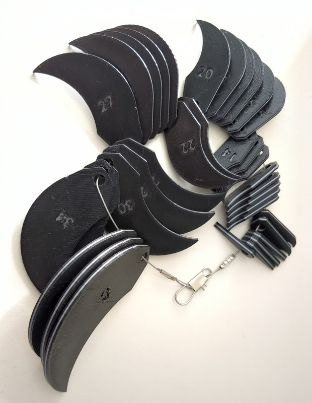
If you design these yourself, accuracy does not matter. You are matching the CAD/Slicer/Printer with what should be repeatable precision. If your #5 radius gauge fits the real world part and matches your CAD/Slicer settings that generated the tool, the fact the tool is not absolutely 5mm has no bearing on the outcome.
The design of all hobby printers is targeting open loop precision with no consideration for accuracy. This is why IDEX is so hard; because the accurate location of both print heads becomes critical. The accuracy problem has been solved long ago with closed loop control, but this is pricey compared to open loop machines. These printers are only precision machines. The only time it is worth calibrating for accuracy is when you need to transfer design files for someone else to print on a different machine. I don't share most of my designs because accuracy is a waste of time. I can use a unit test print, alter my design to compensate, and have a perfect part much faster than fussing with accuracy.
Now that I think about it it makes sense from this perspective.