litchralee

joined 1 year ago
[–] litchralee@sh.itjust.works 14 points 2 days ago* (last edited 2 days ago) (1 children)

Notwithstanding the possible typo in the title, I think the question is why USA employers would prefer to offer a pension over a 401k, or vice-versa.

For reference, a pension is also known as a defined benefit plan, since an individual has paid into the plan for the minimum amount will be entitled to some known amount of benefit, usually in the form of a fixed stipend for the remainder of their life, and sometimes also health insurance coverage. USA's Social Security system is also sometimes called the public pension, because it does in-fact pay a stipend in old age and requires a certain amount of payments into the fund during one's working years.

Whereas a 401k is uncreatively named after the tax code section which authorized its existence, initially being a deferred compensation mechanism -- aka a way to spread one's income over more time, to reduce the personal taxes owed in a given year -- and then grew into the tax-advantaged defined contribution plan that it is today. That is, it is a vessel for saving money, encouraged by tax advantages and by employer contributions, if any.

The superficial view is that 401k plans overtook pensions because companies wouldn't have to contribute much (or anything at all), shifting retirement costs entirely onto workers. But this is ahistorical since initial 401k plans offered extremely generous employer contribution rates, some approaching 15% matching. Of course, the reasoning then was that the tax savings for the company would exceed that, and so it was a way to increase compensation for top talent. In the 80s and 90s was when the 401k was only just taking hold as a fringe benefit, so you had to have a fairly cushy job to have access to a 401k plan.

Another popular viewpoint is that workers prefer 401k plans because it's more easily inspectable than a massive pension fund, and history has shown how pension funds can be mismanaged into non-existence. This is somewhat true, if US States' teacher pension funds are any indication, although Ontario Teacher's Pension Plan would be the counterpoint. Also, the 401k plan participants at Enron would have something to complain about, as most of the workers funds were invested in the company itself, delivering a double whammy: no job, and no retirement fund.

So to answer the question directly, it is my opinion that the explosion of 401k plans and participants in such plans -- to the point that some US states are enacting automatic 401k plans for workers whose employers don't offer one -- is due to 1) momentum, since more and more employers keep offering them, 2) but more importantly, because brokers and exchanges love managing them.

This is the crux: only employers can legally operate a 401k plan for their employees to participate in. But unless the employer is already a stock trading platform, they are usually ill-equiped to set up an integrated platform that allows workers to choose from a menu of investments which meet the guidelines from the US DOL, plus all other manner of regulatory requirements. Instead, even the largest employers will partner with a financial services company who has expertise on offering a 401k plan, such as Vanguard, Fidelity, Merrill Edge, etc.

Naturally, they'll take a cut on every trade or somehow get compensated, but because of the volume of 401k investments -- most people auto-invest every paycheck -- even small percentages add up quickly. And so, just like the explosion of retail investment where ordinary people could try their hand at day-trading, it's no surprise that brokerages would want to extend their hand to the high volume business of operating 401k plans.

Whereas, how would they make money off a pension fund? Pension funds are multi-billion dollar funds, so they can afford their own brokers to directly buy a whole company in one-shot, with no repeat business.

[–] litchralee@sh.itjust.works 4 points 6 days ago* (last edited 6 days ago) (1 children)

Almost. By virtue of being a smaller antenna, the 30 cm panel does not focus its energy as tightly as a larger (eg 60 cm) antenna. Likewise, a smaller antenna does not pick up (ie receive) as much energy as a larger antenna does. Thus, by using a 30 cm panel, less of the high energy from the opposite radio will reach the receiver, and that keeps the receiver from being damaged.

In RF engineering, there is a careful balance between output power, antenna size/shape, environmental conditions, and desired link quality. Whoever built the radio link originally did not apparently perform the necessary calculation. I'm not an RF engineer, but for spanning a mere 50 meters, this 20 cm antenna with built-in radio should be more than sufficient for a basic link.

[–] litchralee@sh.itjust.works 8 points 6 days ago* (last edited 6 days ago) (3 children)

Normally, increased RF power is helpful to overcome interference or noise. Just like how normally, an automobile or airplane will be easier to operate if it has a bigger engine with more power.

At some point, though, the extra RF or engine power is no longer beneficial but also isn't harmful. And if you go significantly beyond that, then you end up in a region where the extra power is downright harmful and is actively working against you.

Consider an automobile driving in a rainstorm. Having more power is bad, because the tires can lose grip more easily, leading to a crash. In an airplane that has gotten into a stall, applying power is the wrong solution and just aggravates the stall, which is not good.

Here, adding more RF power is just cooking the other receiver like it's a Thanksgiving turkey. The extra power is no longer helpful for making communications, and may be physically damaging the receiver.

[–] litchralee@sh.itjust.works 4 points 6 days ago* (last edited 6 days ago)

Although copyright and patents (and trademarks) are lumped together as "intellectual property", there's almost nothing which is broadly applicable to them all, and they might as well be considered separately. The only things I can think of -- and I'm not a lawyer of any kind -- are that: 1) IP protection is mentioned vaguely in the US Constitution, and 2) they all behave as property, in that they can be traded/reassigned. That's it.

With that out of the way, it's important to keep in mind that patent rights are probably the strongest in the family of IP, since there's no equivalent "fair use" (US) or "fair dealing" (UK) allowance that copyright has. A patent is almost like owning an idea, whereas copyright is akin to owning a certain rendition plus a derivative right.

Disney has leaned on copyright to carve for themselves an exclusive market of Disney characters, while also occasionally renewing their older characters (aka derivatives), so that's why they lobby for longer copyright terms.

Whereas there isn't really a singular behemoth company whose bread-and-butter business is to churn out patents. Inventing stuff is hard, and so the lack of such a major player means a lack of lobbying to extend patent terms.

To be clear, there are companies who rely almost entirely on patent law for their existence, just like Disney relies on copyright law. But type foundries (companies that make fonts) are just plainly different than Disney. Typefaces (aka fonts) as a design can be granted patents, and then the font files can be granted copyright. But this is a special case, I think.

The point is: no one's really clamoring for longer parents, and most people would regard a longer exclusive term on "ideas" to be very problematic. Esp if it meant pharmaceutical companies could engage in even more price-gouging, for example.

[–] litchralee@sh.itjust.works 11 points 6 days ago

The original tech installed a 60cm panel for a rf link which is no more than 50M.

In case anyone else has this minor confusion, this is a radio link between two buildings which are 50 meters apart. And a square, directional flat-panel antenna that is 60 centimeters on a side is grossly overkill for the short distance involved.

[–] litchralee@sh.itjust.works 1 points 1 week ago (1 children)

To be clear, the legs would support the topper when it's positioned over the tub, and also support the topper when it's beside the tub? If that's the case, do the legs really need to fold away? Would fixed legs be acceptable? Or is there a requirement that the legs be foldable to provide clearance over the edge of the tub?

[–] litchralee@sh.itjust.works 17 points 1 week ago* (last edited 1 week ago) (3 children)

If you hold a patent, then you have an exclusive right to that invention for a fixed period, which would be 20 years from the filing date in the USA. That would mean Ford could not claim the same or a derivative invention, at least not for the parts which overlap with your patent. So yes, you could sit on your patent and do nothing until it expires, with some caveats.

But as a practical matter, the necessary background research, the application itself, and the defense of a patent just to sit on it would be very expensive, with no apparent revenue stream to pay for it. I haven't looked up what sort of patent Ford obtained (or maybe they've merely started the application) but patents are very long and technical, requiring whole teams of lawyers to draft properly.

For their patent to be valid, they must not overlap with an existing claim, as well as being novel and non-obvious, among other requirements. They would only file a patent to: 1) protect themselves from competition in future, 2) expect that this patent can be monetized by directly implementing it, or licensing it out to others, or becoming a patent troll and extracting nuisance-value settlements, or 3) because they're already so deep in the Intellectual Property land-grab that they must continue to participate by obtaining outlandish patents. The latter is a form of "publish or perish" and allows them to appear like they're on the cutting edge of innovation.

A patent can become invalidated if it is not sufficiently defended. This means that if no one even attempts to infringe, then your patent would be fine. But if someone does, then you must file suit or negotiate a license with them, or else they can challenge the validity of your patent. If they win, you'll lose your exclusive rights and they can implement the invention after all. This is not cheap, and Ford has deep pockets.

[–] litchralee@sh.itjust.works 5 points 1 week ago

I'll address your question in two parts: 1) is it redundant to store both the IP subnet and its subnet mask, and 2) why doesn't the router store only the bits necessary to make the routing decision.

Prior to the introduction of CIDR -- which came with the "slash" notation, like /8 for the 10.0.0.0 RFC1918 private IPv4 subnet range -- subnets would genuinely be any bit arrangement imaginable. The most sensible would be to have contiguous MSBit-justified subnet masks, such as 255.0.0.0. But the standard did not preclude using something unconventional like 255.0.0.1.

For those confused what a 255.0.0.1 subnet mask would do -- and to be clear, a lot of software might prove unable to handle this -- this is describing a subnet with 2^23 addresses, where the LSBit must match the IP subnet. So if your IP subnet was 10.0.0.0, then only even numbered addresses are part of that subnet. And if the IP subnet is 10.0.0.1, then that only covers odd numbered addresses.

Yes, that means two machines with addresses 10.69.3.3 and 10.69.3.4 aren't on the same subnet. This would not be allowed when using CIDR, as contiguous set bits are required with CIDR.

So in answer to the first question, CIDR imposed a stricter (and sensible) limit on valid IP subnet/mask combinations, so if CIDR cannot be assumed, then it would be required to store both of the IP subnet and the subnet mask, since mask bits might not be contiguous.

For all modern hardware in the last 15-20 years, CIDR subnets are basically assumed. So this is really a non-issue.

For the second question, the router does in-fact store only the necessary bits to match the routing table entry, at least for hardware appliances. Routers use what's known as a TCAM memory for routing tables, where the bitwise AND operation can be performed, but with a twist.

Suppose we're storing a route for 10.0.42.0/24. The subnet size indicates that the first 24 bits must match a prospective destination IP address. And the remaining 8 bits don't matter. TCAMs can store 1's and 0's, but also X's (aka "don't cares") which means those bits don't have to match. So in this case, the TCAM entry will mirror the route's first 24 bits, then populate the rest with X's. And this will precisely match the intended route.

As a practical matter then, the TCAM must still be as wide as the longest possible route, which is 32 bits for IPv4 and 128 bits for IPv6. Yes, I suppose some savings could be made if a CIDR-only TCAM could conserve the X bits, but this makes little difference in practice and it's generally easier to design the TCAM for max width anyway, even though non-CIDR isn't supported on most routing hardware anymore.

[–] litchralee@sh.itjust.works 14 points 1 week ago* (last edited 1 week ago) (1 children)

To start off, I'm sorry to hear that you're not receiving the healthcare you need. I recognize that these words on a screen aren't going to solve any concrete problems, but in the interest of a fuller comprehension of the USA healthcare system, I will try to offer an answer/opinion to your question that goes into further depth than simply "capitalism" or "money and profit" or "greed".

What are my qualifications? Absolutely none, whatsoever. Although I did previously write a well-received answer in this community about the USA health insurance system, which may provide some background for what follows.

In short, the USA healthcare system is a hodge-podge of disparate insurers and government entities (collectively "payers"), and doctors, hospitals, clinics, ambulances, and more government entities (collectively "providers"), overseen by separate authorities in each of the 50 US States, territories, tribes, and certain federal departments (collectively "regulators"). There is virtually no national-scale vertical integration in any sense, meaning that no single or large entity has the viewpoint necessary to thoroughly review the systemic issues in this "system", nor is there the visionary leadership from within the system to even begin addressing its problems.

It is my opinion that by bolting-on short-term solutions without a solid long-term basis, the nation was slowly led to the present dysfunction, akin to boiling a frog. And this need not be through malice or incompetence, since it can be shown that even the most well-intentioned entities in this sordid and intricate pantomime cannot overcome the pressures which this system creates. Even when there are apparent winners like filthy-rich plastic surgeons or research hospitals brimming with talented expert doctors of their specialty, know that the toll they paid was heavy and worse than it had to be.

That's not to say you should have pity on all such players in this machine. Rather, I wish to point to what I'll call "procedural ossification", as my field of computer science has a term known as "protocol ossification" that originally borrowed the term from orthopedia, or the study of bone deformities. How very fitting for this discussion.

I define procedural ossification as the loss of flexibility in some existing process, such that rather than performing the process in pursuit of a larger goal, the process itself becomes the goal, a mindless, rote machine where the crank is turned and the results come out, even though this wasn't what was idealized. To some, this will harken to bureaucracy in government, where pushing papers and forms may seem more important that actually solving real, pressing issues.

I posit to you that the USA healthcare system suffers from procedural ossification, as many/most of the players have no choice but to participate as cogs in the machine, and that we've now entirely missed the intended goal of providing for the health of people. To be an altruistic player is to be penalized by the crushing weight of practicalities.

What do I base this on? If we look at a simple doctor's office, maybe somewhere in middle America, we might find the staff composed of a lead doctor -- it's her private practice, after all -- some Registered Nurses, administrative staff, a technician, and an office manager. Each of these people have particular tasks to make just this single doctor's office work. Whether it's supervising the medical operations (the doctor) or operating/maintaining the X-ray machine (technician) or cutting the checks to pay the building rent (office manager), you do need all these roles to make a functioning, small doctor's office.

How is this organization funded? In my prior comment about USA health insurance, there was a slide which showed the convoluted money flows from payers to providers, which I've included below. What's missing from this picture is how even with huge injections of money, bad process will lead to bad outcomes.

financial flow in the US healthcare system Source

In an ideal doctor's office, every patient that walks in would be treated so that their health issues are managed properly, whether that's fully curing the condition or controlling it to not get any worse. Payment would be conditioned upon the treatment being successful and within standard variances for the cost of such treatment, such as covering all tests to rule out contributing factors, repeat visits to reassess the patient's condition, and outside collaboration with other doctors to devise a thorough plan.

That's the ideal, and what we have in the USA is an ossified version of that, horribly contorted and in need of help. Everything done in a doctor's office is tracked with a "CPT/HCPCS code", which identifies the type of service rendered. That, in and of itself, could be compatible with the ideal doctor's office, but the reality is that the codes control payment as hard rules, not considering "reasonable variances" that may have arisen. When you have whole professions dedicated to properly "coding" procedures so an insurer or Medicare will pay reimbursement, that's when we've entirely lost the point and grossly departed from the ideal. The payment tail wags the doctor dog.

To be clear, the coding system is well intentioned. It's just that its use has been institutionalized into only ever paying out if and only if a specific service was rendered, with zero consideration for whether this actually advanced the patient's treatment. The coding system provides a wealth of directly-comparable statistical data, if we wanted to use that data to help reform the system. But that hasn't substantially happened, and when you have fee-for-service (FFS) as the base assumption, of course patient care drops down the priority list. Truly, the acronym is very fitting.

Even if the lead doctor at this hypothetical office wanted to place patient health at the absolute forefront of her practice, she will be without the necessary tools to properly diagnose and treat the patient, if she cannot immediately or later obtain reimbursement for the necessary services rendered. She and her practice would have to absorb costs that a "conforming" doctor's office would have, and that puts her at a further disadvantage. She may even run out of money and have to close.

The only major profession that I'm immediately aware of which undertakes unknown costs with regularity, in the hopes of a later full-and-worthwhile reimbursement, is the legal profession. There, it is the norm for personal injury lawyers to take cases on contingency, meaning that the lawyer will eat all the costs if the lawsuit does not ultimately prevail. But if the lawyer succeeds, then they earn a fixed percentage of the settlement or court judgement, typically 15-22%, to compensate for the risk of taking the case on contingency.

What's particularly notable is that lawyers must have a good eye to only accept cases they can reasonably win, and to decline cases which are marginal or unlikely to cover costs. This heuristic takes time to hone, but a lawyer could start by being conservative with cases accepted. The reason I mention this is because a doctor-patient relationship is not at all as transactional as a lawyer-client relationship. A doctor should not drop a patient because their health issues won't allow the doctor to recoup costs.

The notion that an altruistic doctor's office can exist sustainably under the FFS model would require said doctor to discard the final shred of decency that we still have in this dysfunctional system. This is wrong in a laissez-faire viewpoint, is wrong in a moral viewpoint, and is wrong in a healthcare viewpoint. Everything about this is wrong.

But the most insidious problems are those that perpetuate themselves. And because of all those aforementioned payers, providers, and regulators are merely existing and cannot themselves take the initiative to unwind this mess, it's going to take more than a nudge from outside to make actual changes.

As I concluded my prior answer on USA health insurance, I noted that Congressional or state-level legislation would be necessary to deal with spiraling costs for healthcare. I believe the same would be required to refocus the nation's healthcare procedures to put patient care back as the primary objective. This could come in the form of a single-payer model. Or by eschewing insurance pools outright by extending a government obligation to the health of the citizenry, commonly in the form of a universal healthcare system. Costs of the system would become a budgetary line-item so that the health department can focus its energy on care.

To be clear, the costs still have to be borne, but rather than fighting for reimbursement, it could be made into a form of mandatory spending, meaning that they are already authorized to be paid from the Treasury on an ongoing basis. For reference, the federal Medicare health insurance system (for people over 65) is already a mandatory spending obligation. So upgrading Medicare to universal old-people healthcare is not that far of a stretch,

[–] litchralee@sh.itjust.works 1 points 1 week ago (1 children)

Good luck with your endeavors! Always keep in mind that when debugging a complex problem, try isolating individual components and testing them individually. This can be as easy as swapping a web application with the Python SimpleHTTPServer to validate firewall and reverse proxy configuration.

[–] litchralee@sh.itjust.works 1 points 1 week ago (3 children)

Thank you for that detailed description. I see two things which are of concern: the first is the IPv6 network unreachable. The second is the lost IPv4 connection, as opposed to a rejection.

So staring in order, the machine on the external network that you're running curl on, does it have a working IPv6 stack? As in, if you opened a web browser to https://test-ipv6.com/ , does it pass all or most tests? An immediate "network is unreachable" suggests that external machine doesn't have IPv6 connectivity, which doesn't help debug what's going on with the services.

Also, you said that all services that aren't on port 80 or 443 are working when viewed externally, but do you know if that was with IPv4 or IPv6? I use a browser extension called IPvFoo to display which protocol the page has loaded with, available for Chrome and Firefox. I would check that your services are working over IPv6 equally well as IPv4.

Now for the second issue. Since you said all services except those on port 80, 443 are reachable externally, that would mean the IP address -- v4 or v6, whichever one worked -- is reachable but specifically ports 80 and 443 did not.

On a local network, the norm (for properly administered networks) is for OS firewalls to REJECT unwanted traffic -- I'm using all-caps simply because that's what I learned from Linux IP tables. A REJECT means that the packet was discarded by the firewall, and then an ICMP notification is sent back to the original sender, indicating that the firewall didn't want it and the sender can stop waiting for a reply.

For WANs, though, the norm is for an external-facing firewall to DROP unwanted traffic. The distinction is that DROPping is silent, whereas REJECT sends the notification. For port forwarding to work, both the firewall on your router and the firewall on your server must permit ports 80 and 443 through. It is a very rare network that blocks outbound ICMP messages from a LAN device to the Internet.

With all that said, I'm led to believe that your router's firewall is not honoring your port-forward setting. Because if it did and your server's firewall discarded the packet, it probably would have been a REJECT, not a silent drop. But curl showed your connection timed out, which usually means no notifications was received.

This is merely circumstantial, since there are some OS's that will DROP even on the LAN, based on misguided and improper threat modeling. But you will want to focus on the router's firewall, as one thing routers often do is intercept ports 80 and 443 for the router's own web UI. Thus, you have to make sure there aren't such hidden rules that preempt the port-forwarding table.

[–] litchralee@sh.itjust.works 1 points 1 week ago (5 children)

I'm still trying to understand exactly what you do have working. You have other services exposed by port numbers, and they're accessible in the form .ducksns.org: with no problems there. And then you have Jellyfin, which you're able to access at home using https://jellyfin..duckdns.org without problems.

But the moment you try accessing that same URL from an external network, it doesn't work. Even if you use HTTP with no S, it still doesn't connect. Do I understand that correctly?


The median age of injured conventional bicycle riders was 30 (IQR, 13-53) years vs 39 (IQR, 25-55) years for e-bicyclists (P < .001). Scooter riders had a median age of 11 (IQR, 7-24) years at the time of injury vs 30 (IQR, 20-45) years for e-scooter riders (P < .001) (Table 1 and Figure 3). As a group, those injured from EV accidents were significantly older than those injured from conventional vehicles (age, 31 vs 27 years; P < .001) (eTable 1 in Supplement 1).

e-Bicycles have lowered barriers to cycling for older adults, a group at risk for physical inactivity.9,10 Biking has clear-cut physical and cognitive health benefits for older adults, so this extension of biking accessibility to older e-bicyclists should be considered a boon of the new technology.22,23 However, as injured e-bicycle riders are older than conventional bicyclists, the unique safety considerations for older cyclists should be a focus of ongoing study.

There is a popular conception that ebikes are ridden recklessly on streets and sidewalks by youths, doing dangerous stunts, riding against traffic, not wearing helmets, and incurring serious injury to themselves and others as a result. This conception is often used to justify legislation to restrict or ban ebike use by minors. However, the data suggests quite the opposite, as it is older riders which are racking up injuries.

The data does not support restrictions on ebikes, but rather their wholesale adoption, especially for audiences which are at risk of inactivity or disadvantaged by a lack of transportation options. Ebikes are not at odds with conventional bicycles.

The California Bicycle Coalition offers this succinct summary:

“We think this backlash against e-bikes is the wrong direction for what we want for safer ways for people biking and sharing the road,” said Jared Sanchez, the policy director for the California Bicycle Coalition. “We don’t believe that adding restrictions for people riding e-bikes is the solution.”

They also have a page on how to fight against "bikelash", aka naysayers of bicycles and bikes: https://www.calbike.org/talking-back-to-bikelash/


I have no prior kayaking experience except occasionally paddling one while camping with friends on still water. That's fun and all, but I'd like to get out on the water on my own, to some of the nearby lakes near me, maybe once a month during the sunny seasons. None of these would have anything remotely considered as "rapids".

My main consideration is transporting a prospective kayak, as I greatly prefer biking rather than driving a car for distances within an hour of me, which includes two or three suitable bodies of water. While I have the capacity to store a conventional hard-shell kayak at home, I'm exploring a folding kayak, since this could go with me in a car for farther locations, on a bike for nearby waters, and even a bus. I feel the hassle of moving a 12 ft hard-shell kayak would discourage me from ever using it outright.

This specific model won't ship until October, which might be a bit late in the season, but it's on sale for $300 out the door, or $273 because of a 10% email coupon for keeping it in my cart for an hour.

I'm aware that this isn't anywhere comparable to conventional kayaks, certainly not in price, rough water handling, and maybe not even longevity. But at this particular juncture, and for that particular price point, I think I have a use-case that aligns well with a folding kayak, and if I do develop the itch for something even better, I can always upgrade later. I can accept that this might be a "kayak-shaped toy", but if it floats on water and moves, I would be happy to start with that.

To that end, my questions for this community are whether there are other comparable folding kayaks I should look at, or reasons I should or shouldn't proceed with this purchase in the coming days.

Any and all advice would be greatly appreciated!

Update: I've ordered it and hope to see how it turns out when it arrives in October


cross-posted from: https://sh.itjust.works/post/22165919

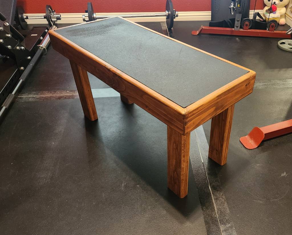
This entry of mine will not match the customary craftsmanship found in this community, but seeing as this was formerly a pile of miscellaneous, warped scrap 2x4 segments recovered from old pallets, I think I've made a reasonable show of things.

This bench is for my homegym, designed to be stood upon, which is why there's a rubber mat inlaid on the surface, a leftover of the gym floor. My design criteria called for even the edge of the top surface to support weight, so the main "box" of the bench uses 2x4 segments mitered (badly) together at 45 degrees, held together with wood glue.

I then routed the inner edge to support a 1/2" plywood sheet, which is screwed into the box. And then the rubber mat is glued down to the sheet, so there are no visible screws.

Finally, the legs are also 2x4 segments, cut so the bench sits 43 cm (~17 inch) from the floor; this is only coincidentally similar to the IPF weightlifting bench standards. I used screws instead of glue, just in case the legs needed to be shortened later.

All edges were rounded over with a 1/2" bit, as the bench is expected to be picked up and moved frequently. And everything stained in cherry and clear-coated.

Some of the annoyances from using scrap included:

  • Stripping old paint off. Awful chemicals, awful scrubbing, awful disposal.
  • Sanding away twists along the 2x4 segments
  • Filling nail holes or arranging them so they don't draw attention
  • My lack of experience with clamping and gluing wood that's not dimensionally consistent

wood bench beside a leg press

If I were to do this again, I'd figure out a way to reduce the amount of routing needed for the inner edge, since I essentially removed 0.75 inch by 1.5 inch of material all around the edge. This took forever, and perhaps a CNC machine would have simplified things, in addition to squaring and planing the surfaces before mitering.

77
submitted 2 months ago* (last edited 2 months ago) by litchralee@sh.itjust.works to c/woodworking@lemmy.ca
 

This entry of mine will not match the customary craftsmanship found in this community, but seeing as this was formerly a pile of miscellaneous, warped scrap 2x4 segments recovered from old pallets, I think I've made a reasonable show of things.

This bench is for my homegym, designed to be stood upon, which is why there's a rubber mat inlaid on the surface, a leftover of the gym floor. My design criteria called for even the edge of the top surface to support weight, so the main "box" of the bench uses 2x4 segments mitered (badly) together at 45 degrees, held together with wood glue.

I then routed the inner edge to support a 1/2" plywood sheet, which is screwed into the box. And then the rubber mat is glued down to the sheet, so there are no visible screws.

Finally, the legs are also 2x4 segments, cut so the bench sits 43 cm (~17 inch) from the floor; this is only coincidentally similar to the IPF weightlifting bench standards. I used screws instead of glue, just in case the legs needed to be shortened later.

All edges were rounded over with a 1/2" bit, as the bench is expected to be picked up and moved frequently. And everything stained in cherry and clear-coated.

Some of the annoyances from using scrap included:

  • Stripping old paint off. Awful chemicals, awful scrubbing, awful disposal.
  • Sanding away twists along the 2x4 segments
  • Filling nail holes or arranging them so they don't draw attention
  • My lack of experience with clamping and gluing wood that's not dimensionally consistent

wood bench beside a leg press

If I were to do this again, I'd figure out a way to reduce the amount of routing needed for the inner edge, since I essentially removed 0.75 inch by 1.5 inch of material all around the edge. This took forever, and perhaps a CNC machine would have simplified things, in addition to squaring and planing the surfaces before mitering.


cross-posted from: https://sh.itjust.works/post/20965205

This is the story of how I turned a 15" Titan adjustable dumbbell to be 80 cm (31.5 inch) long. Why? Because I have a space-constrained home gym but still wanted a leg press, and so I had to remove its original barbell.

In its place, I built a pair of wood mounts for a normal barbell to rest upon, covered in that earlier post. However, since this machine is wall-adjacent, such a barbell would have to fit inside the width of the leg press, so about 80 cm. But must also be wider than the spacing from outside-edge to outside-edge of the wood mounts, which is 60 cm.

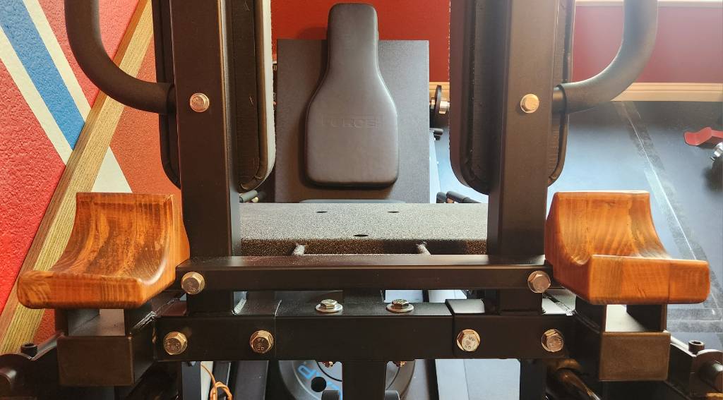
wooden mounts where a leg press barbell would be

Such a short barbell -- or long dumbbell -- does not readily exist commercially, with the narrowest one I've seen being 48 inch barbells, which are still too wide. So I decided to build my own, using my spare Titan dumbbell as the base.

To start, the Titan dumbbells are excellent in this capacity, as the shaft diameter is 28 mm -- not 32 mm as the website would indicate -- which is a common diameter, if I am to cut short a cheap barbell to replace this dumbbell's shaft.

In keeping with my preexisting frugality, I purchased a cheap 1-inch barbell, hoping that it adopts the Olympic 28 mm shaft diameter, and not the 29 mm deadlift bar shaft diameter, as the Titan collars have small clearances. Matching neither, I find that this bar is closer to 23 mm, which although will fit into the existing collars, poses its own issues.

Nevertheless, this 7 ft barbell can conveniently be cut in half to yield two 42 inch segments. And then the included bar stops can be loped off, and then the length further refined to 77 cm, thus hiding the marks from the bar stop within the Titan collars, and also centering the (meh) knurling from the cheap bar.

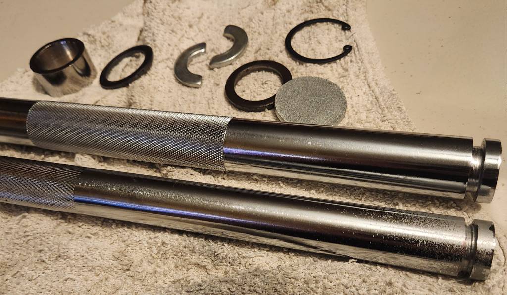
But perhaps a picture will be more explanatory. Here, the original collar is dismantled at the top, showing the original shaft with a groove cut into it, about 1/4-inch from the end. Into that groove would fit two half-rings with an inner diameter of 20.4 mm and an outer diameter of 40 mm. In fact, all the parts inside the collar use 40 mm outer diameter, except the spacer cylinder, which is smaller at 37 mm. All of these parts are held captive within the collar using the C-ring and the geometry of the collar itself.

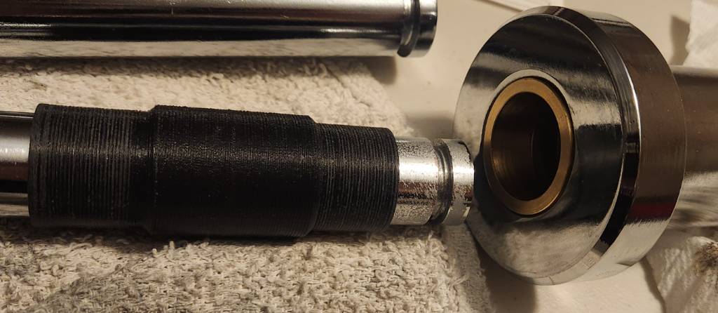
To deal with the difference between the collar expecting 28 mm, and the cheap bar's 23 cm, I designed an ABS 3d printed part in FreeCAD to act as a bushing, upon which the original Titan brass bushing will ride upon. This ABS bushing is held captive by way of its center bulge, which fits within the dead space inside the collar.

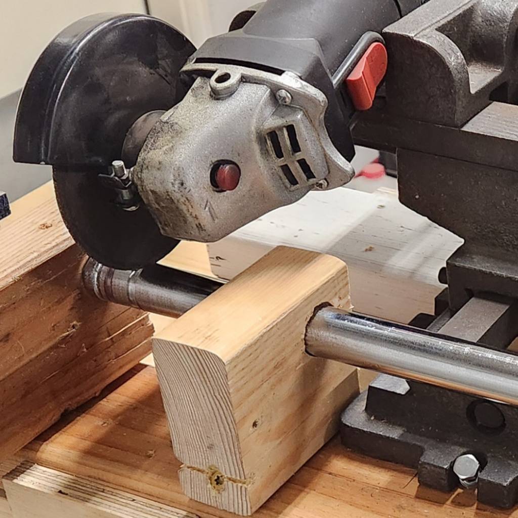
As for how I cut the groove into the end of the new shaft, I still don't own a lathe. So the next best is to mount an angle grinder onto a "cross slide vise" taken from a drill press, with the shaft secured in a wooden jig to only allow axial rotation manually. The vise allows precision control for the cutting wheel's depth, with me pausing frequently to measure how close the groove is to the desired 20.4 mm inner diameter. This is.... not a quick nor precise process. But it definitely works.

After reassembling both collars onto the new shaft and lubricating with white lithium, the final result is a long dumbbell (or short barbell) with Titan's 3.5 inch collars on the end, with 63 cm of shaft exposed and 80 cm from end to end. The ABS bushing is remarkably smooth against the brass bushing, after some sanding with 180 grit. The whole dumbbell weights 5.48 kg empty.

Here is the comparison with the stock Titan dumbbell. It's pretty amazing how the knurling conveniently lined up. It fits well onto the wood mounts of the leg press.

Don't ever talk to me or my son ever again

But why would I do all this just to add a weirdly long 3.5-inch collar dumbbell to a leg press, when it already can accept weights underneath the carriage? I will answer that in a follow-up post.


As is their custom, FortNine delivers a two-wheeler review in the most cinematic way possible, along with a dose of British sitcom humor.

I'm not sure I'd ever buy one, but I'd definitely borrow it from a friend haha. I've said before that I like seeing what novel ideas people will build atop two wheels, and this certainly is very unique.


The title describes the gist of things. In 18 months of owning my Bikonit MD750, I've traveled over 2100 km (1300 miles) in day, night, and rain; swapped out four sets of tires trying to lower the rolling resistance; built my own new set of 29" wheels with ebike-speed rated tires; and have taken it on mixed-mode adventures by using light-rail as my range extender.

It's the latter where the weight is a small issue, as the light rail train has three stairsteps onboard, which I have to carry the bike up and onto. 43 kg is kinda a lot, although that does include all the things I will need for a day out. I can pursue getting stronger to lift it more easily, or convincing the transit department to acquire low-floor trains, but I'd like to know my options:

What are some Class 3, mid-drive ebikes currently available in the USA, that weigh less than 43 kg (95 lbs)? Ideally, less than 25 kg (55 lbs) too, as that's the most common weight restriction for buses. I want to see what y'all can recommend, irrespective of price or range or other considerations.

I'm not likely to terminate my investment in this current ebike, as it's provided sterling service thus far. But I wonder if maybe what I have has already been outmoded by the latest developments in this ever-changing slice of the mobility space.

TY in advance!


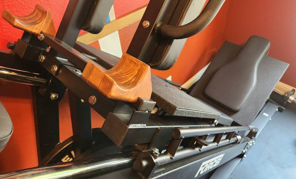
One thing I've always wanted for my space-constrained homegym is a leg press. But even the most compact leg presses occupy a lot of space lengthwise and width-wide. I had my eye on the Force USA 45 degree leg press/hack squat combo machine, because it has so much capacity for me to grow into. So I picked one up and modified it so it can be placed up against the wall.

The primary issue is the barbell that attaches to the carriage (the part that moves up and down). This barbell extends about 45 cm (18 inch) beyond the left and right sides of the machine, taking up stationary space as well as dynamic space when the carriage is in motion. Eliminating that barbell would reduce the width requirement from the bare minimum of 162 cm to 80 cm, assuming the weight storage pegs are also removed.

But of course, the barbell is how the leg press is loaded, with 34 cm on each end for Olympic-spec plates. It also provides some structural stability for the hack squat shoulder pads, where they attach to the carriage. However, dangling underneath the carriage is a much-smaller space for loading plates, with 20 cm on left/right for plates.

Force USA leg press under-carriage plate holder

As an aside, this is a fairly substantial machine that arrived on a pallet, taking a few hours to assemble. The build quality is exemplary, and everything about it evinces durability and stability.

My approach was to remove the original barbell, loading only the under-carriage bar. To retain structure, I cut 1"x2" rectangular steel tube to the width of the carriage (59 cm), capped the ends, and drilled holes to reuse the same bolts as the original barbell. The reason for 1"x2" is because the backrest for the hack squat requires clearance; the stock barbell solved this by bending around that area, whereas 1x2 just barely clears the backrest, and that's good enough for me.

top-down view of replacement steel tube and mounts

Later, I added a pair of wooden mounts where a conventional barbell can be rested. This is not my proudest woodworking achievement, but it's certainly the most unconventional. Each mount is made from three layers of reclaimed 2x6 lumber (from a bed frame) glued together, then a 3.5-inch diameter hole bored through axially, then sanded, stained in cherry, and finished with Polycrylic clear coat for durability. I'll explain the point of these mounts in a different post.

left-side wooden mount on the leg press

The result of all this is a leg press that needs only about 1 meter by 2.4 meter (39" by 96") of floor space, and that's including weight storage pegs on the side away from the wall, plus space to swing the safety stopper bars in/out of place. And everything can be reverted back to the factory configuration.

The caveat is that I'm consigned to the 40 cm total barbell space under the carriage. To maximally load this machine, I would need to invest in thin iron plates, which apparently only are made to precise values, and are thus expensive. Examples: Rogue calibrated KG plates, and Hansu Power calibrated plates, both of which are 22.5 mm wide for 20 kg plates. Sixteen such plates would make 320 kg (700 lbs), and I'd be thrilled if I could get there one day. The tradeoff is reasonable to me, minimizing floor space today in exchange for requiring expensive plates in the future, until I upsize my space.


cross-posted from: https://sh.itjust.works/post/20133956

With the exception of the weight stack for my functional trainer and its change plates, I wanted all my subsequent equipment to be metric. To that end, I saw some cheap 45 lbs CAP bumper plates, and figured that I could make them into metric with not too much effort.

Some rough math prior to purchasing suggested that these plates -- with a width of 68 mm -- could be slimmed down from 20.4 kg (45 lbs) to nearly 20.0 kg, by boring two 2" holes (51 mm). To keep balance, the holes should be on on diametrically opposite ends. And should be neither too close to the edge, nor too close to the center, since the plate still needs to absorb a drop without deforming. That the bored holes are 51 mm is a fantastic happenstance, nearly identical to the center hole for Olympic-spec plates.

Examining each plate before drilling, I found that the silkscreen letter A in "CAP" is well-centered diametrically, although it doesn't line up with the matching logo on the back side. Also, since these are cheap CAP plates, the initial weight tolerances are pretty poor. 45 lbs should be 20.41 kg (2 sig figs), but my first four plates registered at 20.58, 20.51, 20.64, 20.56. That's nearly an extra half pound!

To drill the holes perfectly plumb, I did the work on a drill press using a 2-inch hole saw. Because the saw wasn't deep enough to go through the full width in one pass, I started with a 1/4-inch (6 mm) pilot hole straight through the tip of the letter A in "CAP". Then I drilled from both sides with the hole saw until a ~200 gram rubber core fell out. Repeat for the second bore.

To finish, I took some sandpaper to remove the old "45 lbs" markings, then used my label maker to affix new values. All plates are still high, but ranged from 20.030 kg to 20.105 kg. Not too shabby, I think.

In a happy coincidence, the position of these bored holes is perfect for one's thumbs when grasping the plate like a steering wheel, making it easier to pick up when laid flat on the floor. I also added a strip of blue electrical tape around the perimeter to make it easy to identify these as 20 kg.

In the end, I got the cheap metric plates I wanted, and it came with a usability improvement as well. I've not dropped these yet, so time will tell how they hold up.


This September 2023 report by staff at the US Consumer Product Safety Commission compiles injury and fatality data involving micromobility devices, using data that was available at the time of publication. As the report notes multiple times, the aggregate data is fairly coarse and CPSC staff could only follow up on so many reports.

Nevertheless, the report offers some rather interesting insights on e-scooters, hoverboards, and ebikes, although at 42 pages, some might prefer to just read the Executive Summary -- which is just 4 pages -- and skim the figures and tables.

Some of my takeaways from the report:

  • ER visits for e-scooters have been at least double that of ebikes, although ebike data was below the reporting minimum so that data was estimated (page 10)
  • E-scooters and hoverboards ER visits by female/male are 35%/65% and 55%/45%, but ebikes are disproportionate at 24%/76% (page 12)
  • Two-thirds of hoverboard ER visits are for 5-14 year olds, the largest group of any age range for any micromobility device (page 13)
  • The vast, vast majority of ebike ER visits were incurred while riding on a public road or public property. No surprise there. (page 14)
  • July has the most ebike ER visits (14% of annual total), and January/February the least (3% each of annual total) (page 15)
  • The report has a whole section dedicated to e-scooters, starting at page 17
  • One-third (32%) of treated e-scooter injuries indicated the rider was carrying or holding onto something, with 61% indicated not holding, and 7% unspecified (page 21)
  • 13% of treated e-scooter injuries indicated the rider was wearing a helmet, with 51% unspecified (page 22)
  • Between 2017 and 2022, using available data, CPSC found 104 deaths related to ebikes. These deaths skew heavily male (84 deaths) and 25+ years old (87 deaths) (page 23-24)
  • 58 of 104 ebike deaths involved collisions with motor vehicles, the leading cause. The data does not specify whether the ebike or motor vehicles or both were in motion at time of collision (page 25)
  • 8 of 104 ebike deaths involved pedestrian collisions, composed of six pedestrians and two ebike riders
  • 2 of 104 ebike deaths involved fire by the ebike batteries
  • 18 of 104 ebike deaths involved collisions with terrain, roadway features, or wayside obstacles (page 25)
  • Of 59 ebike injury reports that CPSC staff followed up, 28 identified fire hazards, the leading cause. 24 of 59 involved non-brake mechanical issues, such as bicycle components failing or detaching (page 28)
view more: next ›