The "typical application circuits" on page 2 in the datasheet https://ww1.microchip.com/downloads/en/DeviceDoc/MCP1700-Data-Sheet-20001826F.pdf shows both input and output being decoupled with a 1µF cap, have you tried that? I haven't worked with the MCP1700, but I have had other LDOs fry themselves because the decoupling malfunctioned.
Ask Electronics
For questions about component-level electronic circuits, tools and equipment.
Rules
1: Be nice.
2: Be on-topic (eg: Electronic, not electrical).
3: No commercial stuff, buying, selling or valuations.
4: Be safe.
I initially tried with those capacitors but decided to also try without them - perhaps you're right and I broke my LDOs by doing that :/
I'm not saying that your LDOs are fried. What I am saying is that some LDOs don't take too kindly on not having the company of some nice caps.
What just caught my eye is that the datasheet specifies ceramic non-polar caps. That seems a bit weird. Just drawing a non-polar would have made sense, but specifying that it is a ceramic is strange. Using a ceramic makes sense, I mean there are 5 times the ceramic 1uF caps on digikey than there are electrolytics, but it should be technologically agnostic... I'd probably try to get some 1uF ceramics for testing.
Unlikely. Have you measured the voltage present at Vin?
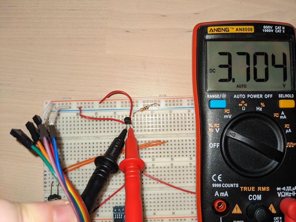
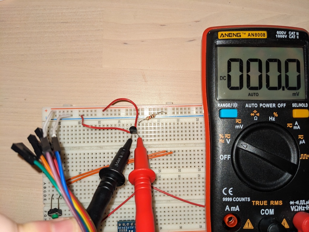
Yes, I measured across ground and Vin and it shows ~4V. Across ground and Vout 0V.
Just to be sure: positive probe on Vin, negative probe on GND, measurement shows no minus sign?
Yes, that's what I did and what it shows. I also attached a picture of my test setup just in case I did something wrong there
Huh, that's weird. Double checking the part markings would've been my next suggestion, but the picture shows they're correct. Maybe try a 1kOhm load resistor across Vout and GND, though in theory you should be able to see the output voltage without it.
I tried with the resistor, same thing, 0V. I made two images showing the measurements


