Arduino and other electronics projects info

125 readers
1 users here now

founded 2 years ago
MODERATORS
1


First replies only links about charging projects

2
3


Outline

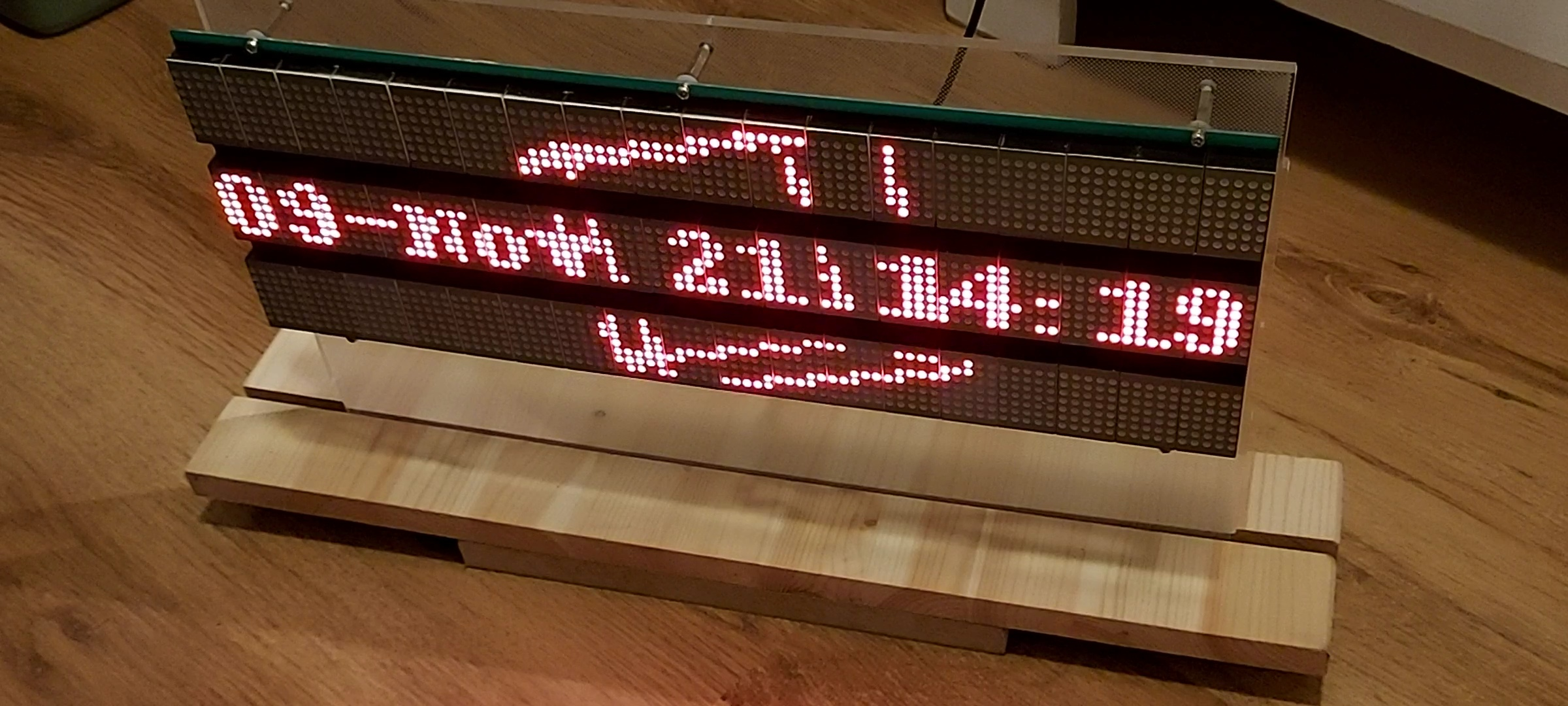
Used hardware

Panel frontside

Panel backside

  • The larger 4 pin connector is for 9 volt power supply. All LED's lit takes about 3.5-4 Amps!
  • The smaller 4 pin connector has: "gnd", "latch/enable", "clock", "data"
  • The data pushed in via "clock" and "data" has the following parts: ~tail~[control byte][bit 89]..[bit 0]~head~
    • [control byte] has following bits: [1 bit n/u] [4 bit counter value][3 bit line select]
      • [4 bit counter value] is decremented each clock pulse if 'enable' is active. Once the counter reaches '0', the line-select will be suppressed. This is used for built-in brightness control
      • [3 bit line select] the bits at this position dictate which of the 7 lines (traversing all 3 text-rows) is/are lit.

Standalone panel

  • The plexiglas plate was taken from a defective LCD monitor

Involved MCU's

  • ESP8266 : NodeMCU 1.0(ESP-12E Module)
    • USB-serial receives bitmap-packages and forwards these to the Wemos using "ESPNOW"
  • ESP32 : Wemos D1 mini
    • Receives bitmap packages and displays it on the LED-panel
    • SPI-pins connect to the LED-panel clock- and data-line
    • Separate output pin connects to the LED-panel latch/enable pin

Notes

  • The Wemos D1 mini runs the LED Panel controller software.
    • On CPU0 runs a task which pushes out the data via SPI.
    • CPU1 is used by the WIFI/ESPNOW library to receive the display-packages.
    • A display package consists of [1 byte for payload length][1 byte for brightness 0-15][237 bytes of which 90 bits represent the 90x21 pixels picture].
    • Because of maximum SPI clock speed, the hardware brightness logic, and the fact that data-shifting can only be done while the 'enable' is off, the display refresh rate lies at about 60hz.
  • The NodeMCU runs a simple package forwarder at 115200 kbps. Receiving via Serial/USB and forwarding via ESPNOW. The first byte read is the length of the payload. Then it reads 'length'-bytes. Once received, it forwards the package via ESPNOW to the dedicated MAC address of the Wemos. "ESPNOW" maximum package size is 250 bytes, so fits nicely.
  • Python is used to provide the NodeMCU with frame-packages. The rendered image is 90x31 pixels. 2 bars of 5 pixels high are removed from the image, so that the LED-less areas are removed from the image and the destination image becomes the required 90x21 pixels.
    • One Python program uses Pillow image library to generate the animation with the time centered, and a rotating 3d-cube.
    • One Python program uses OpenCV to read a .mp4 video, to obtain the frames one by one. Each frame is scaled down to 90-pixels-wide, cropped to 90x31, turned into 2 color B&W before sending.
4
5
6
7
8
9
10
11
12
13
14
15
16
17


Feb 21, 2018 This is an electrostatic polarity detector with increased sensitivity. This device makes it possible to investigate the polarity of the high voltage. RED LED = Positive, BLUE LED = Negative, Both LED = Alternating Voltage On the HVDC line, only one LED will be on. How to make an Electrostatic Polarity Detector :

Jun 7, 2017 This is a simple Electrostatic Polarity Detector(Electric Field Detector) made of FDS8958A Chip. This chip(FDS8958A) contains N- and P- Channel Enhancement mode power field effect transistors. Old Version : Using 9V battery. New Version : Using 3V battery. The circuit diagram appears on the video. 07:13

IRF 7317 is replacement part for FDS8958A - Thomas Kim 2017

See improved schematic by Thomas Kim in 2018 https://lemmy.staphup.nl/comment/66129

18
19
20
21
22
23
24


Apr 3, 2012 For more from the AT&T Archives, visit http://techchannel.att.com/archives

On an elementary conceptual level, this film reflects the multifaceted scientific hyperthinking that was typical of a Bell Labs approach. Host Dr. J.N. Shive's presence as a lecturer is excellent - it's understandable by a layperson even when he branches into equations, because he uses copious amounts of real-world examples to bolster the material.

Shive's role at Bell Labs was more than just a great lecturer: he worked on early transistor technology, inventing the phototransistor in 1950, and the machine he uses in the film is his invention, now called the Shive Wave Machine in college classrooms.

Dr. J.N. Shive of Bell Labs demonstrates and discusses the following aspects of wave behavior:

Reflection of waves from free and clamped ends Superposition Standing waves and resonance Energy loss by impedance mismatching Reduction of energy loss by quarter-wave and tapered-section transformers Original audience: college students

Produced at Bell Labs

Footage courtesy of AT&T Archives and History Center, Warren, NJ

25
view more: next ›